When a handset powers on, the first thing it does is find a base station. It does not know which cells are nearby or what their identities are, so it scans the spectrum for a small synchronization block each cell transmits periodically. In 5G that block is the SSB: it bundles the primary and secondary synchronization signals and the broadcast channel across four OFDM symbols and 240 subcarriers.
Re-implementing that cell-search receiver on an FPGA by hand is tedious enough that the project sits on the shelf. Instead we pointed our algorithm-to-silicon flow at the reference design and let it generate the receiver directly, targeting the Kria KV260. Then we fed it a real 5G downlink captured off the air, a 30 kHz-spacing signal carrying three cells.
Generated in layers, checked at every layer
The flow does not write hardware in one leap. It builds the receiver in three layers and has a machine check each layer against the one above it: a floating-point reference model whose output matches the 3GPP definitions and the MATLAB 5G Toolbox; a cycle-accurate fixed-point model checked bit-for-bit against the reference model; and the Verilog RTL, checked bit-for-bit against the cycle model. Every adjacent pair of layers is reconciled by machine, not by assertion.
What the receiver does
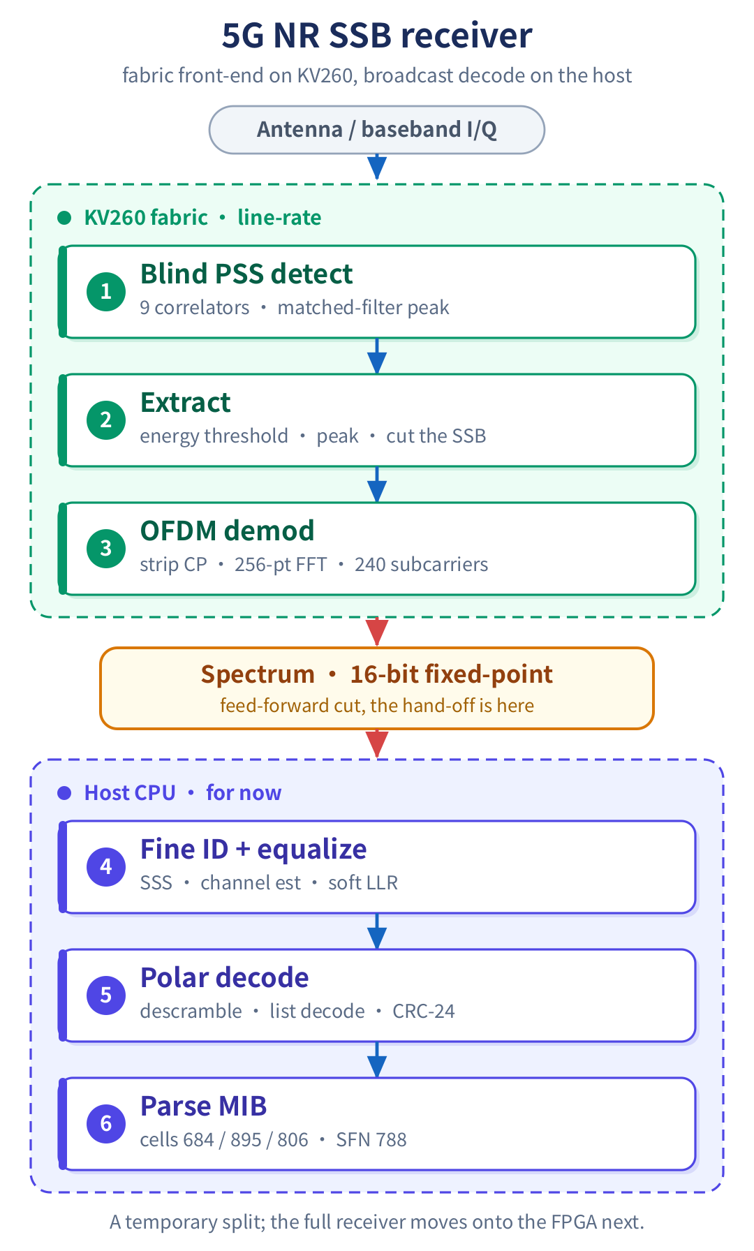
The input is a stream of baseband I/Q samples. Turning that into a cell identity and a decoded broadcast message takes four stages. Because the receiver does not know the cell group at power-on, it correlates against all three primary-synchronization candidates at once. Each is a complex matched filter, and a complex matched filter factors into three real sub-correlations, so the front end runs nine folded correlators in parallel to find the synchronization peak. An energy measure and a peak finder then cut the block out, a 256-point FFT recovers the 240 subcarriers, and the broadcast decode recovers the message.
Split across two tiers, for now
First, why the KV260 at all: we usually run these radio designs on a small ADALM-Pluto SDR, but its FPGA is too small to hold the whole 5G NR receiver, so we used the larger KV260 to validate the design on real silicon for now. The chain is also not one monolithic block on the FPGA. Detection and demodulation are fixed-rate streaming work that moves every clock, which suits the fabric. The broadcast decode is control-heavy: it searches 336 secondary-synchronization candidates and runs a polar list decoder, which is cheaper on a CPU. For now the design is cut at the recovered spectrum, and the decode runs on the host because the control-heavy code was faster to bring up in software for now. The front end emits a 16-bit fixed-point spectrum; the host still decodes the broadcast message with a clean CRC, because the pilot equalization and the polar code carry enough coding gain to absorb the quantization noise.

Read from three real cells off the air
Validation runs two ways. Against the MATLAB 5G Toolbox as an independent judge, thousands of standard-compliant blocks, each carrying a known cell identity and broadcast message, are decoded and compared bit for bit. And against the real captured signal: the receiver read all three cells in the capture to one consistent broadcast message, system frame number 788 and 30 kHz spacing for each. That consistency is itself the check, because cells synchronized in one area should broadcast the same message.
The work also corrected an error in the reference script, which parsed the scrambled payload without descrambling and produced a wrong, per-cell-different frame number. Adding the descrambling and de-interleaving the standard specifies is what makes the three cells agree.
How weak a signal it still decodes
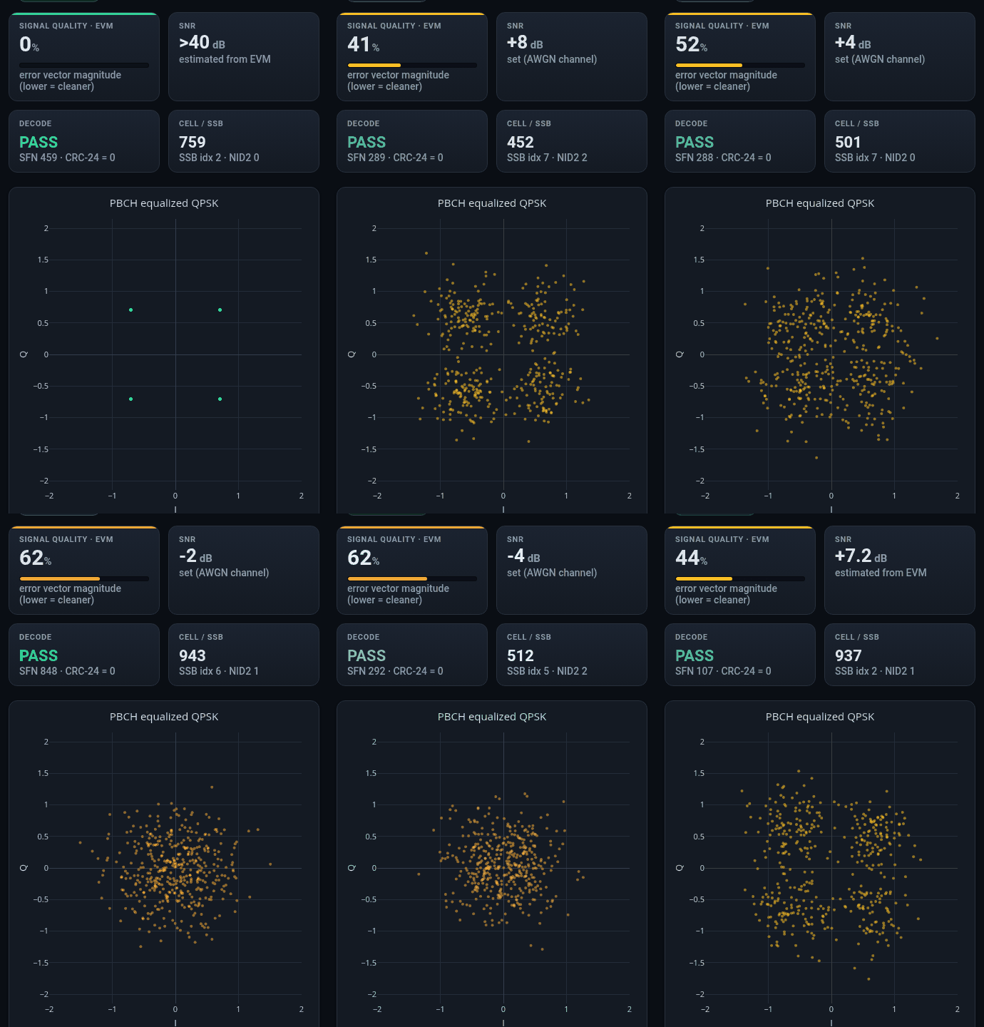
The real capture is one operating point. To measure robustness, 1,460 diverse vectors from the MATLAB toolbox cover all 1,008 cell identities, every SSB position, any broadcast message, two subcarrier spacings, plus a noise sweep, carrier offset, and frequency-selective fading. On a clean channel, 300 of 300 random configurations decode bit-exact. Under the noise sweep the block error rate is zero down to -2 dB per resource element and only starts to climb near -6 dB, which is the noise floor a low-rate broadcast channel is designed to reach.

Leaner than an earlier HLS build
The nine correlators are the algorithmically required cost of blind detection, and they are where the resources go. Each one is generated as the family's most efficient folded FIR, so on the same part the detector uses 38% fewer look-up tables and 75% fewer flip-flops than an earlier hand-written HLS implementation, with one block RAM against seven. The full receiver, detector plus demodulation, closes place-and-route at 256 MHz on the KV260, and the deployed overlay meets timing at the 200 MHz link rate.
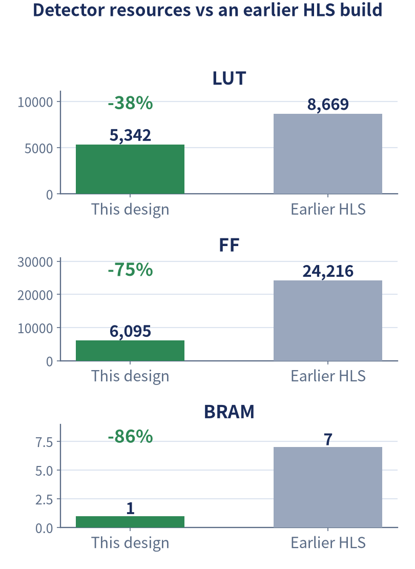
On real silicon, the reference signal was streamed through the KV260 front end over DMA and the computed spectra were read back and compared to the reference model: 2,540 beats, zero mismatch.
See it run on real captured signals
The analyzer below replays a stream of diverse synchronization blocks, the same host decode chain that runs on the KV260 spectra, with no server and no radio attached. As the channel worsens the constellation spreads from a tight QPSK to a noise cloud, the signal-quality history climbs, and the broadcast decode holds bit-exact down to the coding limit before it finally fails.
Why this is repeatable
This was a 5G receiver, but nothing in the method is specific to 5G. From the standard definition, to a fixed-point model with timing, to the generated circuit, each layer is bit- equivalent to the one above it, and the equivalence is checked by machine. Running the decode on the host is a development-stage step, not the final architecture; the full receiver moves onto the FPGA next. And the leaner resource number is not hand-tuned: the flow maps each correlator to its most efficient hardware structure, which is why it comes in below an earlier hand-written HLS build. What carries over is the method, not this one receiver.