A fault-tolerant quantum computer reads an error signal every measurement cycle and must infer the most likely physical errors before the next cycle arrives. For superconducting qubits that budget is on the order of a microsecond per round. The decoder is therefore a hard real-time classical machine, not an offline solver, and it is one of the things standing between today's lab machines and a useful one.
This is the story of re-building IBM's Relay-BP decoder for the [[144,12,12]] gross code, from the algorithm down to placed-and-routed silicon, with our algorithm-to-hardware flow. The honest result up front: it lands on the same silicon envelope as the published reference, and the genuine contribution is a clean map of which optimizations move the needle and one algorithmic lever that does.
What the decoder actually does
Plain belief propagation is the workhorse of classical error-correction decoding: every check shares what it knows with every error bit, the bits update their beliefs, and after a few rounds the most likely error pattern falls out. On quantum codes it stalls. The structure of the code creates symmetric traps where the beliefs oscillate and never settle. Relay-BP adds three ideas that break the symmetry.
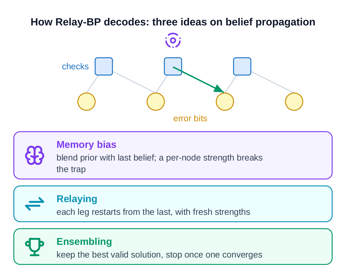
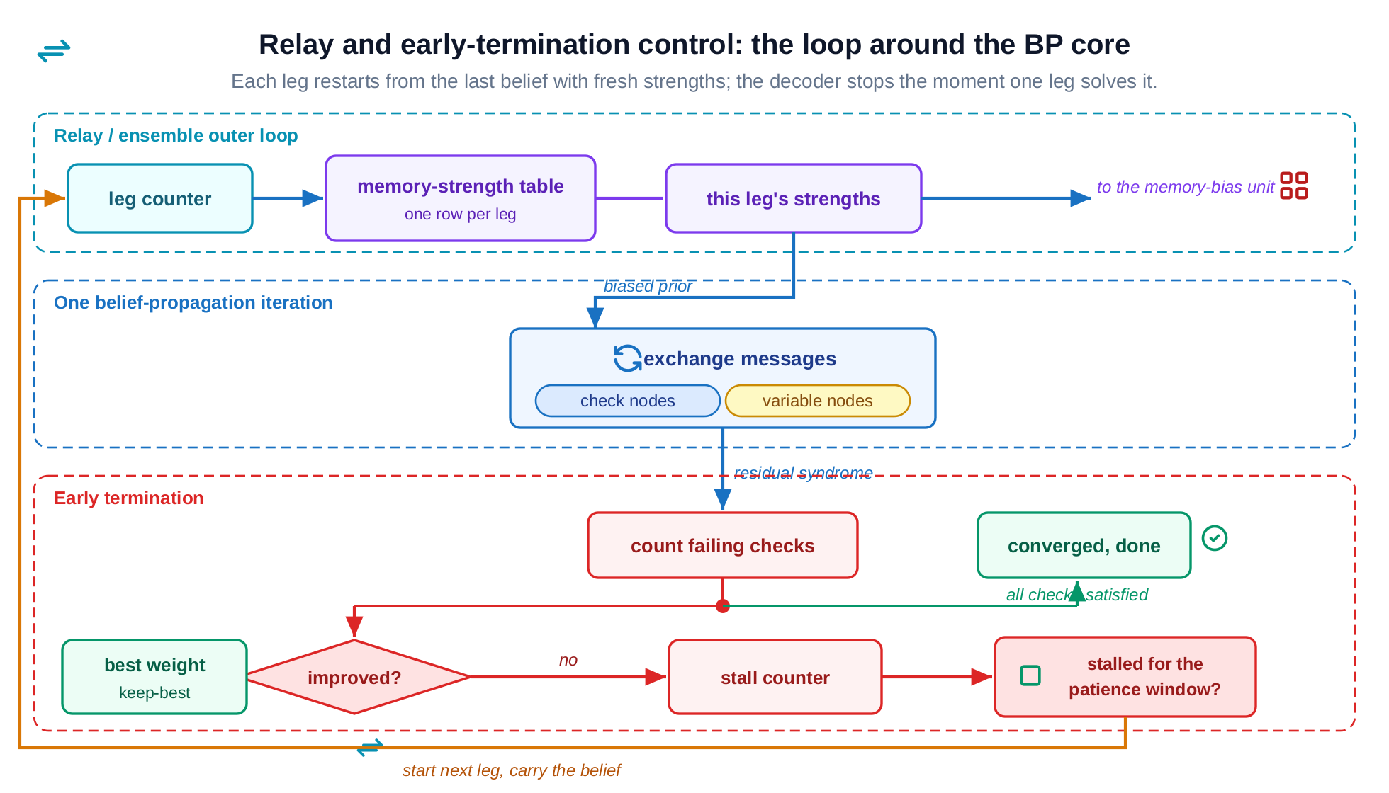
The memory bias blends each bit's prior with its previous belief by a per-node strength that is allowed to be negative. Relaying runs the decode as several legs, each starting from the last leg's beliefs with freshly drawn strengths, which is like trying a new path to the answer. Ensembling keeps the lowest-weight valid solution and stops the moment one leg converges. On the gross code this beats general-purpose post-processing decoders by about an order of magnitude in logical error rate (IBM, arXiv:2506.01779).
The machine, up close
Everything that follows is a property of four small units repeated across the code graph. Look at them at the circuit level first: the cost, the wall, and the win all point back to one of these four.
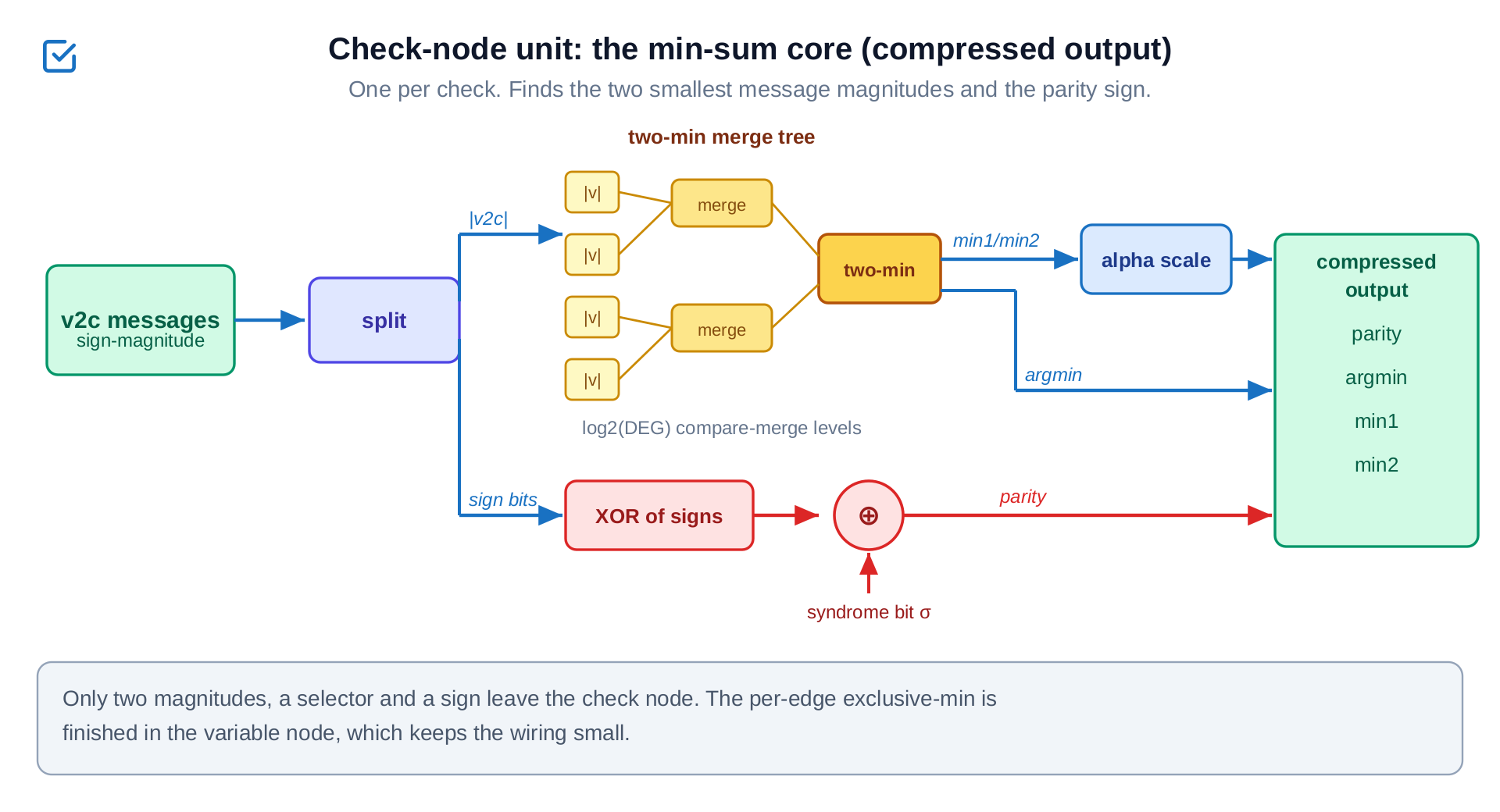
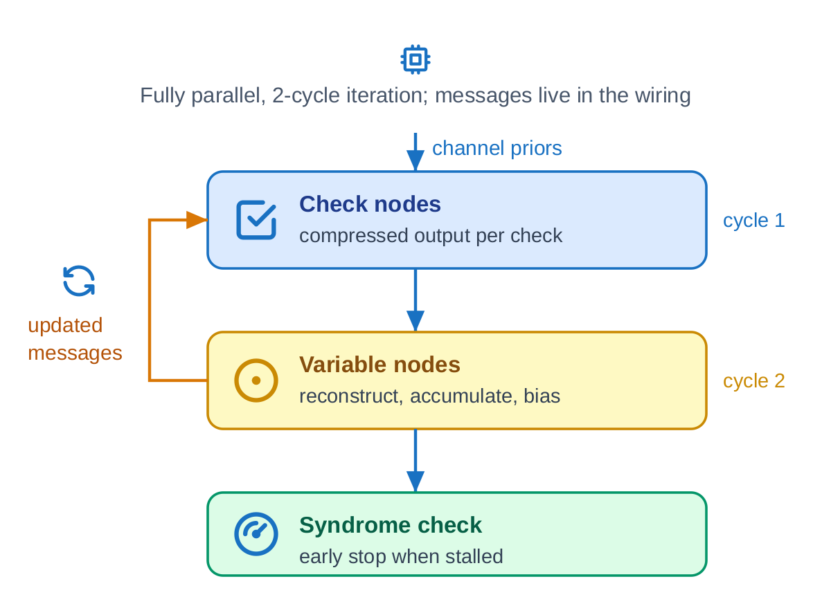
The check unit is one per check. It finds the two smallest incoming magnitudes and compresses them into a compact form. Finishing the per-edge detail is deferred to the bit side, which is what keeps the output bus narrow and the wiring affordable.
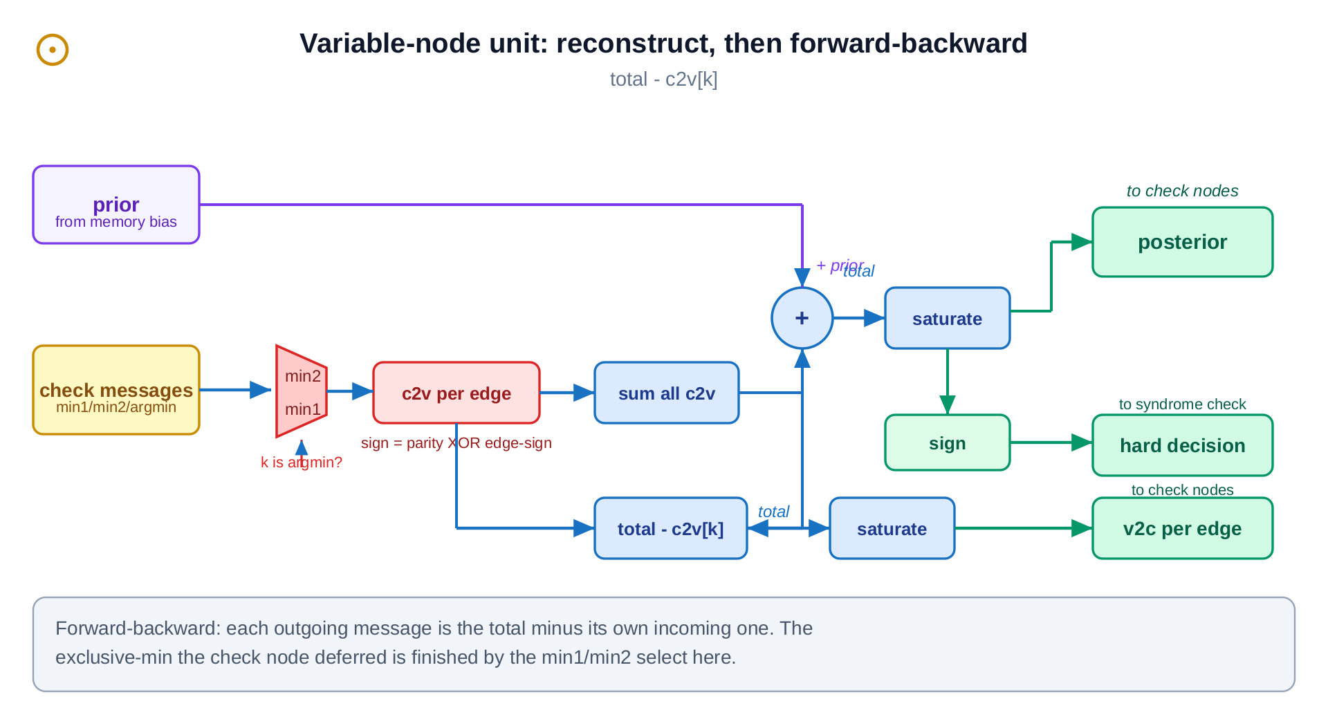
The bit unit is one per error bit. It reconstructs each incoming message, sums them with its prior, and produces each outgoing message and the current hard decision. That rebuild step is what pays back the check unit's compression.
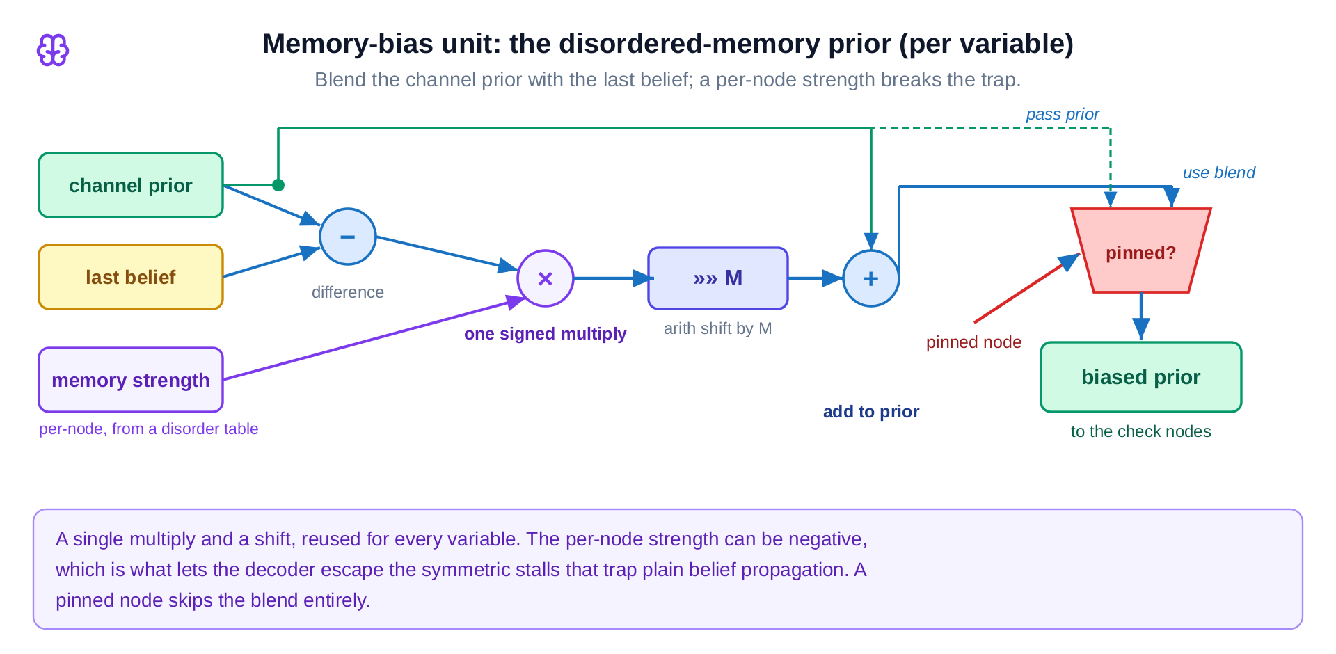
The memory-bias unit is the Relay-BP idea in hardware, one per bit. It blends the prior with the last belief, and a pinned bit passes its prior straight through. The per-node strength can be negative, and that is precisely what lets a decode escape the symmetric stall.
The control wraps the loop. It sequences the legs, feeding per-leg strengths to the memory-bias unit and carrying the belief from one leg to the next. It remembers the best attempt so far, tracks how long progress has stalled, and ends the decode the moment the error signal clears. This is where the one real optimization lives.
Why the hardware is large, and where the clock goes
The reference silicon decoder is fully parallel: one compute unit per graph node, one wire per edge, a whole round in two clock cycles. There is no central message memory. The messages live in the wiring itself, which is why the design is dominated by routing rather than logic.
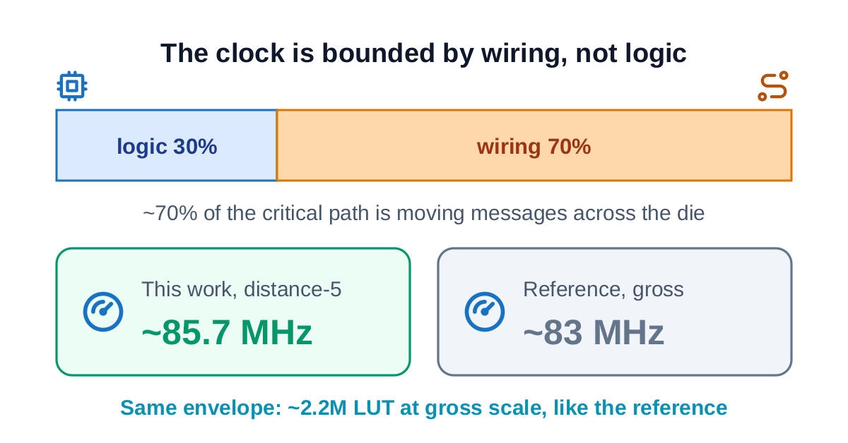
We measured a synthesizable distance-5 build, a faithful proxy for the gross code, and compared it against the published gross-code silicon. About 70% of every critical path is wire delay moving messages across the die, an intrinsic property of this kind of code graph. The clock is bounded by wiring, not by logic. That is why the result lands on the reference envelope rather than beating it: the wiring is the wall, and it is the same wall for anyone building this fully parallel.
What moved the latency, and what did not
Decode latency is iterations times cycles-per-iteration divided by clock. With the clock pinned by routing, the honest map of what moves latency is short, and several intuitive levers actively hurt.
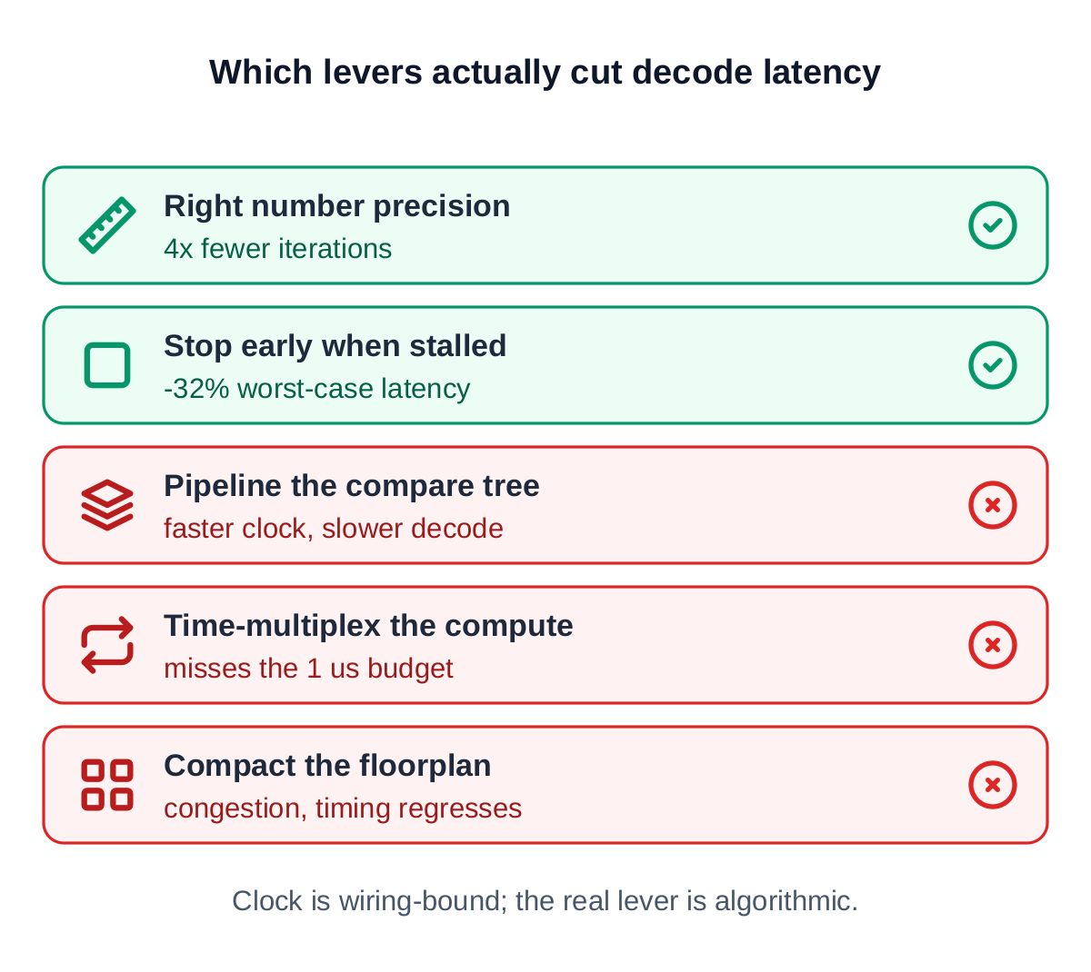
The precision that cut iterations to a quarter was a real win. Several intuitive levers were measured and turned out to be dead ends for a latency-first design: some saved area but converged slower, some raised the clock at the cost of an extra cycle, and some could not meet the microsecond budget at all. The lever that works is algorithmic: end an attempt the moment it stops making progress.
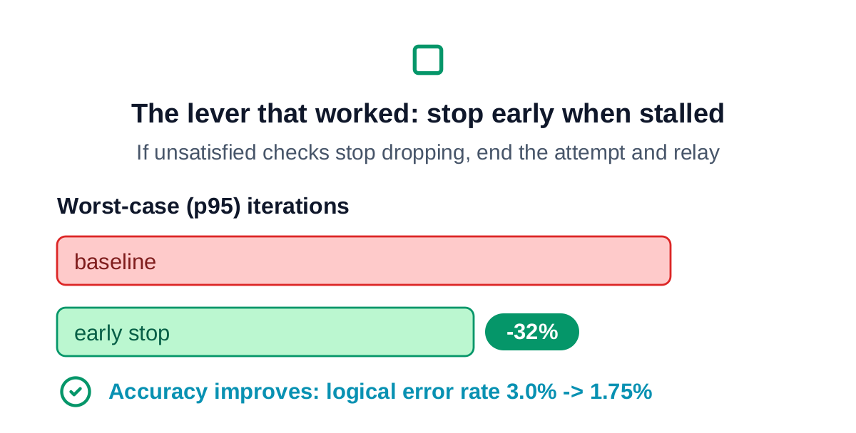
Early termination cut worst-case iterations by about 32% with no accuracy loss. The logical error rate actually improved, because each fresh relay explores a new path to a valid solution. In hardware it costs a count of the failing checks and a small counter, about half a percent of area and a couple of megahertz of clock, a clear trade for a latency-first decoder.
What this says about the method
The decoder, generated from a model proven equal to the math at every layer, sits on the published silicon envelope for the gross code: the same clock regime, the same resource scale. It is not faster, because the wall is the code graph's wiring, which is the same for any fully parallel build. The transferable result is the loop and the honest map: on a wiring-bound design the clock is a property of the graph, so spend effort on fewer iterations or fewer wires, not on pipelining or floorplanning, and validate any early-stopping policy on the logical error rate at scale, not just on convergence. Every number here traces to a measured run, and every layer is held to the one below it bit-for-bit.